Der Einfügungsdämpfung von dünn- Filmfilter wird hauptsächlich durch drei Kategorien von Faktoren bestimmt: intrinsischer Materialverlust, Verlust der Strukturkonstruktion und Verlust bei der Prozessimplementierung Die
Dies bezeichnet den unvermeidbaren „Reibungsverlust“ bei der Signalübertragung durch das Medium. In der optischen Kommunikation entsteht er primär durch Photonenabsorption und -streuung in dielektrischen Schichtmaterialien (z. B. SiO₂, Ta₂O₅). In Hochfrequenzanwendungen (z. B. BAW/SAW-Filtern) resultiert er aus Phononenverlusten in piezoelektrischen Materialien (z. B. LiNbO₃, AlN) und Widerstandsverlusten in Elektrodenmaterialien. Dies definiert die theoretische Leistungsgrenze des Bauelements.
Konstruktionsmängel verursachen Signalverluste. Impedanzfehlanpassung (zwischen dem Port und der Systemimpedanz) verursacht Reflexionsverluste, die direkt mit einem schlechten Stehwellenverhältnis (VSWR) zusammenhängen. Unzureichende Außerbanddämpfung Dies ermöglicht es, dass Signalenergie in den Sperrbereich gelangt. Darüber hinaus verbraucht auch die Modenkonversion (z. B. die Abstrahlung von akustischen Volumenwellen in SAW-Filtern) Energie.
Dies ist die primäre Variable in der tatsächlichen Produktion. Oberflächenrauheit (verursacht Streuung durch ungleichmäßige Filmschichten), Schnittstellendefekte (schlechte Zwischenschichthaftung, Nadellöcher) und Musterfehler (Ätzabweichungen, die zu Resonanzfrequenzverschiebungen führen) verursachen zusätzliche Verluste. Faktoren wie thermische Fehlanpassung aufgrund von Temperaturänderungen können die Verlustschwankungen ebenfalls verstärken.
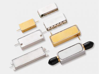
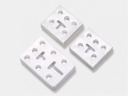
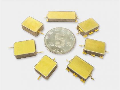
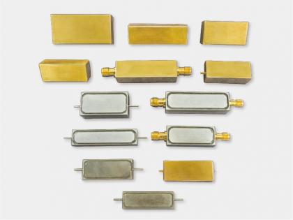
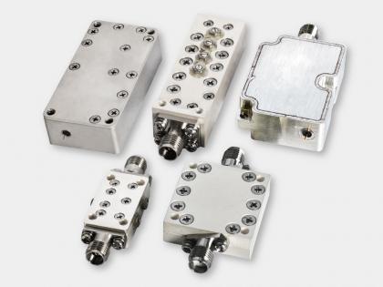
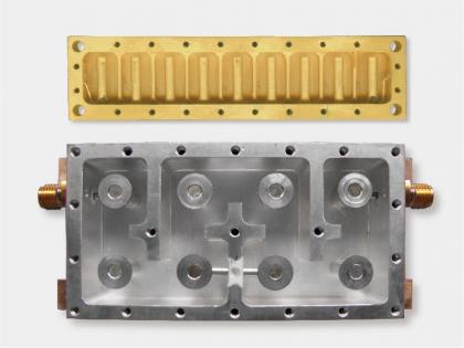
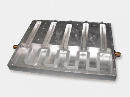
Yun Micro Als professioneller Hersteller von passiven HF-Bauteilen kann ich Folgendes anbieten: Hohlraumfilter bis zu 40 GHz, einschließlich Bandpassfilter, Tiefpassfilter, Hochpassfilter, Bandsperrfilter.
Nehmen Sie gerne Kontakt mit uns auf: liyong@blmicrowave.com

die Anschrift : Xisan Road, Mechanical and Electrical Industrial Park, No.767 Yulan Road, Hefei,Anhui.
Tel : +86-18855146875
Email : liyong@blmicrowave.com


Scannen Sie es